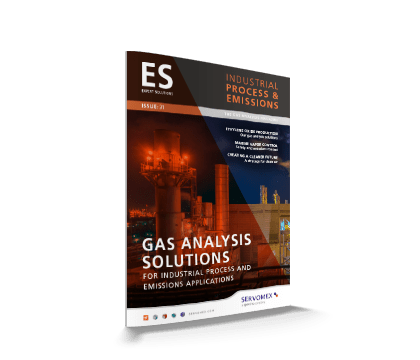
获取您的碳捕获和封存解决方案
获取更多关于我们的碳捕获和封存过程解决方案的信息。点击下载并保持随时能收到我们的通知。
气体分析有助于控制有害排放
不完全燃烧会导致有害污染物释放到环境中。大多数监管机构要求这些污染物由连续排放监测系统(CEMS)监测,包括O2和粉尘以及污染物SO2、NOx、CO和CO2的测量。
高性能解决方案确保产品质量
捕获的二氧化碳可用于制造燃料、碳酸盐、聚合物和其他化学品,因此需要通过气体分析对其质量进行密切监控。如果从燃煤发电等过程中捕获,它可能含有二氧化硫和硫化氢等污染物
我们有解决方案来支持您的工艺要求
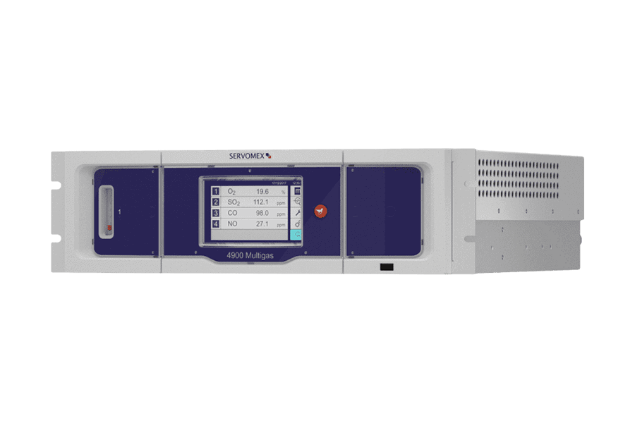
SERVOPRO 4900 Multigas是一款抽取式分析仪,单台设备即可测量多达四种烟道气组分,可满足大多数连续排放监测气体分析需求。SERVOTOUGH SpectraExact 2500光度气体分析仪是质量控制的关键解决方案-结合背压调节器,可提供±0.2%的精度,以及80%至100%的CO2测量范围。我们还提供安全与燃烧控制的分析解决方案。
我们是值得信赖的碳捕获和封存专家
我们在为CSS应用提供分析系统方面有着丰富的经验,我们了解您的过程应用。我们的解决方案已被证明能够提供您所需要的结果。
专家团队
凭借深厚的应用知识,我们的专家可以为您的现场应用提供最佳的解决方案,提供完全符合您要求的气体分析。
精确的解决方案
有了广泛的气体分析技术,我们能够为各种CSS方法提供最精确和正确的测量。
全球支持
我们的高性能分析仪由服务和支持人员网络支持,确保整个流程提供可靠性能。
Search Servomex 碳捕获和封存(CCS) analyzers
按搜索字词优化
Clear filters通过以下方式优化选择:

4900 Multigas
SERVOPRO Safe Area
4900 Multigas是一款高性能CEMS分析仪,设计用于多种多气体测量。
- 先进的数字多气体 CEMS 分析
- 最多同时进行四个气流测量
- 超稳定、准确、无损耗的传感器
- 自动校准可减少操作需求
- 直观的图标驱动彩色触摸屏
- 用于远程访问的数字通信
AquaXact 1688
SERVOPRO Safe Area
坚固耐用的超薄氧化铝氧化铝湿度传感器,可在各种气相工艺应用中测量水分。
- 快速准确的湿度测量
- 坚固耐用的超薄膜氧化铝传感器
- 用作独立的 4-20mA 发射器
- 与兼容的控制器或分析仪远程连接
- 传感器元件可通过 NIST 追溯且可现场更换
- IP65 等级连接器
MultiExact 4100
SERVOPRO Safe Area
一种高性能的多气体分析仪,旨在提供多达四个同时的气流测量。
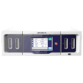
- 高度适应性的多气体分析仪
- 提供多达四个同时测量
- 广泛的传感技术选择
- 工业和医用气体的多功能解决方案
- 内置湿度传感器支持
- 可选的高级数字协议
SERVOTOUGH Oxy 1900
SERVOTOUGH Hazardous Area
The Oxy 1900 oxygen (O2) gas analyzer sets new standards of flexibility, stability and reliability from a single, cost-effective unit.
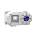
- 1 区/1 区危险区域额定值
- 数字顺磁 O2 测量
- 加热样气室以确保稳定性
- 独特的专利 FlowCube 流量传感器可增强安全性
- 自动验证/校准选项减少了手动维护
- 智能样品排气压力补偿选项
SpectraExact 2500
SERVOTOUGH Hazardous Area
灵活的单组分和多组分气体分析能力,适用于腐蚀性、有毒和易燃样品流。

- 坚固、可靠的光度分析
- 专为持续易燃样品而设计
- 适用于危险区域应用
- 适用于各种气体样品类型
- 使用经过现场验证的非消耗技术
- 经过气体认证
商业道德方法
仕富梅价值观支撑着我们所做的一切:它们指导我们的工作方式,为我们的决策提供基础并塑造我们的文化。
Get the latest news, sign up to emails
您已添加到我们的新闻通讯中
您已添加到我们的新闻通讯中
联系我们-我们可以帮助你的过程
了解更多关于我们的分析仪支持您的碳捕获过程的方式。我们一系列的技术可为您的测量点提供最适合的解决方案。联系我们的应用专家了解更多。
Our latest podcast looks at a variety of carbon capture and storage processes available to industry, and the challenges facing operators using them. Listen now to find out how Servomex provides optimum solutions
Carbon capture podcast transcript
MH: Welcome, once again, everybody to another Servomex podcast, today on the subject of CCUS, which is carbon capture, utilization and/or storage. This is a very, very hot topic around the world at the moment. And I’m once again joined by Maria Mokosh, our application development engineer in EMEA. Hi, Maria.
MM: Hi, Matt. Good morning.
MH: CCUS, as I said, is a very hot topic around the world at the moment, very closely linked with emissions, with decarbonization, and climate change, more importantly. Back in 2015, the Paris Agreement was signed by a large number of nations. And this agreement was put in place to agree to not allow global temperatures to rise beyond another 1.5 degrees Celsius. That implemented a carbon budget, so an amount of CO₂ or a volume of CO₂ that could be emitted over the next few years before that temperature increase was seen. Countries were committed to become net zero by 2050.
If countries were to meet that goal of 2050, the current agreement among the science community is that we would actually use up our carbon budget about a decade too soon. That’s the current thinking. At the start of 2020, there was about 440 billion tons of carbon left in that budget, so we’ve gone nearly two years beyond that already. And even if we used up that budget by 2040, there was still only a 50-50 chance, according to the data, of actually not achieving the temperature increase. So 2030 is the is the current proposed target for being carbon net zero.
And since then, a lot of countries have put in their own pledges, in addition to the Paris agreement, to try and meet that target, the UK being one, for example. Servomex, as a company, with our sister companies and our parent company Spectris Group, have put in our own roadmap to achieve carbon net zero by 2030, and to work with our suppliers and customers to ensure that our value chain is carbon net zero by 2040.
This ties in very nicely with our Clean Air initiative and our Clean Air Solutions, of which there’s a two-part podcast you can go onto our website to listen to, that we we’ve recorded previously. And what Servomex wish to do is work with our customers to take collective action via our Clean Air Solutions to enable gas clean-up and emissions phase solutions. You’ll remember, those of you who have listened to the podcast, we spoke about a three-phase approach, combustion control, gas clean-up, and emissions, and really carbon capture spans the last two of those phases.
Carbon capture, utilization, and storage, quite simply, as the name suggests, is the attempt to capture carbon, typically as it as it leaves the process – or catch CO₂ specifically, as it leaves the process – to stop it being emitted into the atmosphere to stop it contributing to the global warming effect. By the end of 2020, there were approximately 20 plants in operation around the world, and another 40 in development. The current global capacity for carbon capture is considered to be around 40 million tonnes per year, something in that area. But if all those projects were to proceed, the capacity is believed to increase to around 130 million tonnes a year.
Most of these projects are in the US and Europe, those two regions are very much leading the way when it comes to carbon capture. And just a few notable projects, which are considered demonstration projects. What that means is these are projects that aren’t running at full capacity at the moment, they’re just trying to prove that different types of technology for carbon capture work because there’s, as we’ll discuss later, there’s lots of different ways of doing this.
So, the first one to mention is the Tomakomai project, which is in Japan. This is capturing, year on year – it’s been running for a few years now – but year on year, about 100,000 tonnes a year, but achieved 300,000 in its last year. This has now stopped and what they’ve done is they’ve stored the CO₂ underground, and they’re closely monitoring that CO₂ storage at the moment, just to check everything is stable, and there’s no risks or problems involved with storing CO₂.
There’s a project in the UK called Drax, or called the BECCS project, which has a capacity of a tonne of CO₂ a day, which is very, very significant. It’s not running at that capacity yet, but that’s a very big number, currently, in CCS terms. And this has been put in place to target a proposed zero-carbon Humber CCUS hub, which will mean storing captured CO₂ in the North Sea and will be aiming for around 17 million tons of CO₂ per year.
And then there’s the Northern Lights project, which is the first cross-border project that’s being developed in Europe, specifically in Norway, but it will cater for the wider European market. This is a partnership between Equinor, Shell, and Total, and aims to capture 800,000 tonnes a year by 2024 and will store the CO₂ off Norway’s west coast.
What we’re going to talk about today are four main areas of carbon capture technology. The first is pre-combustion capture, the second post-combustion capture, the third oxyfuel combustion, and then a fourth, which is capturing CO₂ that’s already in the air, already in the atmosphere, so extracting it from the air. The industries that Servomex traditionally work with would be included in the first three of those types, but we will touch on the fourth type for balance. So, Maria, I’m hoping you can give me a little intro into these four different types of technology – shall we start with pre-capture?
MM: Yes, indeed, there are these three main industrial ways to capture it: pre-combustion, oxyfuel, and post-combustion, and then there is this little bit apart, which is direct capture from air.
Okay, so let’s start with pre-combustion. Pre-combustion carbon capture, as the name indicates, removes CO₂before combustion of fuel. Coal, oil, or natural gas is heated in pure oxygen, resulting in a mix of carbon monoxide and hydrogen. The syngas, mainly carbon monoxide and hydrogen, plus some CO₂, produced from the gasification process, undergoes a catalytic gas shift process, with water vapor converting most of the carbon monoxide into additional carbon dioxide and hydrogen. So far, this part of the process, also known as steam reforming, has been used for decades to produce hydrogen from coal and natural gas.
The next step, namely the capture of CO₂, combined with the necessary purification of hydrogen, has been added to the established process. The gases are fed into the bottom of reactor. In the reactor the gases will naturally begin to rise. A solvent amine, again, has been established here, is poured into the top. The amine binds the CO₂ and falls to the bottom of the reactor. Hydrogen continues rising up and out of the reactor.
The next step is to heat the amine CO₂ makes, to release CO₂. It rises to the top where it can be collected, compressed, and moved into a reservoir, and the amine drops to the bottom for reuse. Same as for post-combustion carbon capture, desulfurization added before the CO₂ absorber will improve the efficiency and reduce solvent degradation.
Further, the monitoring of CO₂ purity, hydrogen purity, and a purity such as carbon monoxide, hydrogen sulfide, and water vapor, makes sense in the product streams for CO₂ and hydrogen. Hydrogen, together with a non-shifted carbon monoxide, can act as a feed for gas turbine or fuel cell for producing electricity. The resulting emissions, vented to atmosphere, will contain mainly oxygen, nitrogen, and water vapor, and reduced concentrations of CO₂ and NOx. They should be monitored, for example, by traditional infrared, UV and paramagnetic technologies. For safety, ambient oxygen and carbon dioxide leakage should be monitored at the CO₂ storage site.
The advantage of pre-combustion carbon capture is that part of the process is already in use, for example, for SMR – steam methane reforming – and coal gasification. The disadvantage is that, although the pre-combustion carbon capture process is lower in cost, it is not a retrofit for older power plants. As with post-combustion, pre-combustion carbon capture can prevent 80 to 90% of power plants emission from entering the atmosphere. So that’s a pretty good goal.
MH: That was pre-combustion Maria, so what about post-combustion capture?
MM: In post-combustion carbon capture, CO₂ is removed from flue gas which the burning of fossil fuels produces. The CO₂ content can vary depending on the fuel used. Widely proven has been the chemical absorption process, using amines to separate CO₂. However, other options such as membrane absorption are in the process of being rolled out, large scale, so we expect to see more variants in the coming years.
In a typical reaction, CO₂ is bound to an absorbent, for example, amine, at lower temperatures, then at higher temperature CO₂ is released again producing a CO₂ stream of up to 90% purity and leaving the absorbent free again to be recycled and reused for CO₂ capture. The produced pure CO₂ product has to be compressed and fed to a storage reservoir and the remaining flue gas is vented to atmosphere. The flue gas at this point mostly contains nitrogen, argon, and oxygen, especially if NOx and SO₂ scrubbers are included before the absorber. In addition to traditional infrared, UV, and Paramagnetic technologies, which are used to measure the flue gas content from power plants, the same measurement techniques can be used to control emissions after the CO₂capture process.
Some components which are typically included in flue gas can be problematic for amines. SO₂ and NO₂ can be irreversibly absorbed, thus reducing the solvent efficiency. Others, such as H₂S and water vapor, can be absorbed concurrently with CO₂, which will affect the product purity and cause equipment corrosion. Thus, to improve the efficiency and reduce solvent degradation, these components should be removed by pre-filtration or scrubbing.
For process control, it should be recommended to measure the input and remaining impurities and the purity of the CO₂ product. At the storage side, ambient oxygen and CO₂ leakage need to be monitored for safety reasons, due to CO₂ being an asphyxiant. The disadvantage of this process is that it requires a lot of energy, depending on the solvent used. Other separation mediums and separation techniques, such as membrane technology and more modular techniques,are currently being tested large scale – further optimization is expected in the next years. The advantage already is that post-combustion carbon capture can be added to existing power plants and industrial processes.
MH: Okay, thanks Maria, for those explanations. So oxyfuel combustion, quite simply, is the combustion of a fuel with pure oxygen or near-pure oxygen, as opposed to the more traditional combustion air that’s used. In order to get the pure oxygen, what they typically do is use some kind of air separation unit, or something very similar to air separation, cryogenic technology, to denitrify the air, so remove the nitrogen, which makes up the bulk of air that we breathe, and then leaving oxygen and the other trace components, use that to fire and oxidize the fuel.
This brings a number of challenges. For one, there’s a much higher safety concern when combusting with pure oxygen. Pure oxygen is much more reactive than the oxygen in there. So it’s enriched, it makes reactions typically more lively, and increases flame temperature quite dramatically, which can actually affect the way that a fuel combusts. This is currently used, typically, on gaseous fuels, it’s been challenging to use this on solid fuels. One of the reasons as to why it’s been challenging with solid fuels is there’s a concern over how the flame temperature will actually affect the valency of the some of the heavy metals that are in fuels such as coal. So, basically, the valency of a material is how readily it will combine with other materials. If you change the valency of a heavy metal, you risk forming other types of emissions that may have different environmental impacts to the CO₂ that we’re trying to remove, so it’s being piloted, but it’s much more common to find this in gaseous combustion, natural gas for example, and syngas.
So, the reason that oxyfuel combustion is perhaps desirable in terms of carbon capture is because you take the nitrogen away from the reaction, which means you no longer produce NOx, which is it an emission in itself, which is quite heavily regulated around the world. If you remove the potential to form NOx, what you do is produce a gas stream that is relatively CO₂ rich, and the other gases that you form, from other contaminants and hydrocarbons, can be removed using traditional clean-up technologies. For example, sulfur, which will oxidize to form SO₂ can be removed using flue gas desulfurization technologies which have been used for decades. And what that leaves you with is a relatively pure stream of CO₂, which you can then capture, using post-capture technologies. And then you can sequester it, you can store it somewhere you can transport it away, and it involves very little clean-up.
One of the measurement challenges of oxyfuel is the fact that you now have a much higher level of excess oxygen post-combustion. So in a typical combustion reaction using air, you would expect to perhaps have less than 10%, perhaps less than 5%, excess oxygen left over, but when you’re burning or oxidizing with pure oxygen, you’re going to have a lot more; you’re going to have potentially enriched oxygen levels, so greater than 21%, depending on on your level of process control, which means typical and traditional measurement technologies like Zirconia, which are used in in-situ Zirconia combustion analyzers and Servomex’s FluegasExact 2700, become unusable because the way Zirconia technology works, it’s only suitable to measure up to 21% oxygen, which is the level of oxygen that the Zirconia cell is being exposed to on its reference side so it can’t measure more than that.
Servomex do have a way of utilizing the FluegasExact 2700 in this application. We have specially designed software, which will actually allow a Zirconia even being referenced to air to monitor up to 50% oxygen. So, we do have a solution for oxyfuel combustion processes.
Oxyfuel combustion isn’t a new thing; it’s been used in the glass and metal industries for a long time, glass especially, because the very high flame temperatures are needed. Whereas they’re not needed in combustion of fossil fuels for power generation. What they actually need to do is recycle some of the flue gas that’s produced, in order to bring the temperature of the main combustion chamber down, because we just don’t need the very high flame temperatures that can be up in the 1500 Celsius or above. But that is useful in in the glass industry.
Because of the high temperatures, there’s other considerations for plant operators, such as flame temperatures and how the other materials in the process can withstand much higher temperatures. Hence this this recertification of flue gas, which has become common practice.
Oxyfuel combustion can certainly be retrofitted in a way to existing processes with some level of modifications to burners and even turbines further downstream. But it makes it quite an appealing technology to consider when it comes to pairing that with a post-combustion type CO₂ capture.
Aside from the combustion control measurement I’ve mentioned, which is possible in oxyfuel combustion with the FluegasExact 2700 in its modified state, with the software that I mentioned earlier, the Laser 3 Plus can make the measurement as long as the excess oxygen level doesn’t exceed 21%, so it depends on the level of control over the process. And obviously, process to process, that can change.
There’s some other measurements to be made. The O₂ stream, that has been cryogenically separated, is often measured for quality purposes. That can be monitored with Paramagnetic technology, either in the form of an OxyExact 2200, which is capable of measuring enriched oxygen, even in a hazardous area if zoning is an issue… If not, the MultiExact 4100, which is our 19-inch rack-mount unit, fitted with Paramagnetic, can also monitor up to 100% oxygen in a safe area.
And then we have, of course, the traditional emissions monitoring system, so a 4900 Multigas in our case, monitoring CO, NOx, SO₂ and oxygen, but also CO₂ now – so, much higher levels, of course, of CO₂. So we’re looking at using traditional NDIR technology. Then we have the carbon capture measurements, so the CO₂ purity, of course, using the SpectraExact 2500 Infrared analyzer, we then have some of the measurements Maria has already mentioned. Further downstream or in the value chain, we have the pipeline and the CO₂ storage. So again, looking for the CO₂ levels and other contaminants that could cause sweet or sour corrosion in storage and pipelines. And then the storage itself, where we’re looking for oxygen, or can look for oxygen, for safety purposes.
So, Maria, we’ve covered the three industry-level carbon capture technologies. We mentioned a fourth one, right at the beginning, which is this direct air capture plant. Can you tell us a little bit more about that technology?
MM: Well, the CO₂ capture from ambient air is quite an interesting, and quite an ambitious, technology. The fourth option to capture CO₂ is the CO₂ capture from ambient air, which is obviously quite ambitious. Currently, the world’s largest plan to suck CO₂ out of ambient air is running in Iceland. It’s a project called Orca. At the Orca project, a concentrated carbon dioxide stream is mixed with water, and injected at a depth of about 1000 meters into basalt rock. At this depth, CO₂ behaves more like a liquid than a gas; it seeps into the spaces in porous rock and, long-term, the expectation is that it would turn into limestone.
MH: And there’s another one of these plants that’s planned to open in 2024, which is called DAC1, so Direct Air Capture One. And that’s very similar to the method you just described, pulling CO₂ from the air, and then ultimately transporting it via a pipeline and storing it under the Permian Basin.
MM: Yeah, there are supporters, which says that these carbon capture and storage technologies will become a major tool in the fight against climate change. However, critics obviously mention that the technology is still very expensive, and it might take decades to operate at large scale. So we are best to prevent creation of CO₂in the first place.
MH: That’s a very good point, Maria, very good point. And the emissions targets that I mentioned right at the start, driven by that 2015 Paris Agreement and subsequent agreements between individual countries, it’s been made clear that those targets will not be met by reduction alone – although that, of course, is one of the best strategies, to not produce the CO₂ in the first place. But obviously, that’s not realistic; industrial processes will always be there producing fuels, and products, and power that the world needs. So that’s really driven the development of these four carbon capture technologies that we’ve been talking about today, because if we assume some of those emissions will always be emitted, we of course, then can deal with them in other ways, such as capturing them.
MM: Carbon Capture and Storage, as the name indicates, requires some type of storage site for the captured CO₂. So, after CO is captured, the next step is transporting it to a storage site. The current method of transporting CO₂ is through a pipeline or by vessel. Carbon dioxide pipelines do exist, for example, for enhancing oil production. Pipelines can transport CO₂ in three states: gaseous, liquid and solid. Solid CO₂ is commonly known as dry ice, and not very cost-effective to transport via pipeline. Commonly, pipelines transport CO₂ in its gaseous state. A compressor pushes the gas through the pipeline – sometimes an intermittent compressor is used to keep the gas moving.
The transported CO₂ must be free of hydrogen sulfide, and dry, otherwise sweet and sour corrosion of the pipeline can occur. Accidents with CO₂ pipelines have so far been rare, probably due to the low number of existing pipelines. However, because CO₂ is an asphyxiant which you cannot see or smell, there have been recommendations to add an odor to the gas to help detect any leaks. CO₂ detectors and ambient oxygen measurements, as a safety measure, especially where people work and live, are strongly recommended.
Ships or tanker trucks transport CO₂ as liquid. Liquid CO₂ requires low pressure and constant low temperature, so cargo tanks need to be both pressurized and refrigerated. Same as for pipelines, because CO₂ in high concentration is causing asphyxiation, CO₂ detectors and ambient oxygen measurement should be recommended for safety reasons.
Regarding storage, there are two places which have been identified so far: underground and underwater. Underground storage, also called geological sequestration, is already in use by the oil and gas industries to squeeze out any extra oil and gas from depleted reservoirs with the help of CO₂. Oil and gas reservoirs are well suited to store CO₂, as they consist of layers of porous rock formations with overlying rocks that form a seal and keep the gas contained.
Geological sequestration involves injecting CO₂ into underground rock formations. At a depth of about 1000 meters, CO₂ behaves more like a liquid than a gas. It seeps into the porous rocks, which means that a great amount of CO₂ can be stored in a relatively small area. Especially when combined with water, CO₂ can essentially form limestone over the next years.
Apart from the fact that we are just moving our CO₂ problem from the point where it is created to storage, there are also environmental concerns. What happens if the carbon dioxide leaks out underground? We can’t really answer this question today, because the process is new, and we don’t know the long-term effects. However, most experts support that measurement of CO₂ leakage around CO₂ storage sites, and underground, are required for monitoring of any CO₂ movement, and for safety.
CO₂ usage would obviously be the best solution if we could use up all the CO₂ which we are creating and separating. Unfortunately, right now, the creation of CO₂ due to our industrial processes is way higher than what we’re actually using. The CO₂ demand is supposed to increase over the next couple of decades. Right now, most of it is used in fertilizer production. And the next highest usage is in beverages, for fizzy drinks basically. So projections are that the global demand is going to increase, especially for areas where CO₂-derived products are used, for example, carbon-based fuels such as methanol production, also some chemicals such as plastics polymers. There’s also been some recent development in using CO₂ in the creation of building materials, such as CO₂-cured concrete, and also CO₂ for enhancing the yields of biological processes.
The second option for storing CO₂ is underwater. Technically, it is possible, if you could safely release CO₂ at about 3500 meters below water surface, because then CO₂ will compress into a slushy material and fall to the ocean floor. However, the method is very theoretical, has not been tested yet, because of concerns for the safety of marine life and the possibilities that CO₂ could resurface. We have seen that in an accident in the 1980s in Cameroon, where emissions of CO₂ from a lake which was above a volcano killed nearly 2000 people and a lot of animals, they died from asphyxiation. That’s one of the reasons why underwater storage is considered unsafe.
The second reason is that CO₂ can be, even though it has sank to the ocean floor, it still can be soaked in water, and thus increasing the water acidity and affecting any marine life which reuses carbon carbonate, such as shells and corals. So that’s another point not to use underwater storage.
MH: Thank you everybody for listening and tuning into this podcast on CCS and CCU. Thank you very much, Maria, for your inputs today.
MM: Thank you for the invitation.
MH: Please do remember to visit servomex.com to find out more about CCS and CCU – go to the resources section and you’ll find other podcasts, videos, application notes and product brochures. Thank you again and we’ll see you next time.
